

d
DIY CNC Router
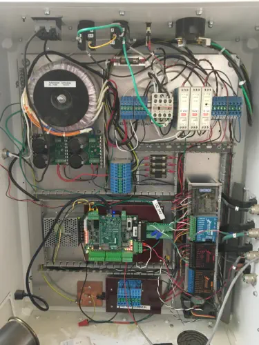
CNC Router Build and Evolution (2015–Present) In 2016, I decided to build a CNC router for my shop. This was not my first machine build—I had previously constructed several shop machines using traditional woodworking and metalworking tools, including a combination wide-belt sander/planer and a pin router. These projects were completed using a South Bend lathe, a metal cutoff saw, and an old drill press. One of my main goals for this CNC build was to create a machine capable of machining both wood and metal. The finished machine ultimately proved capable of milling wood, aluminum, and even steel. Frame and Mechanical Components As with most of my projects, I started by visiting my local surplus store. There I found a fabricated aluminum frame made from TIG-welded I-beams. This frame defined the overall size of the machine: 36" × 80" eBay, as usual, became my primary source for precision components at a fraction of new cost. I purchased three ball screw assemblies complete with bearing blocks. Only the bearing blocks were used; the screws themselves were replaced with Nook Industries XPR precision rolled ball screws, all 5/8" diameter with a 0.200" pitch. This pitch is common in DIY CNC machines and provides excellent resolution. It’s worth noting that ball screws have a critical speed—beyond a certain RPM, the screw will begin to vibrate. With my 67" screw length, vibration became severe at 250 IPM. Reducing the machine’s maximum speed to 200 IPM eliminated the issue entirely. X-Axis Linear Rails The X-axis uses Thomson 1-1/4" round linear motion rails mounted to the underside of the aluminum frame. Installing them required drilling 48 precision holes into the frame. One rail was mounted first, then I built a measuring setup using a dial indicator mounted to an aluminum extrusion connected to two Thomson bearing blocks. After about five hours of adjustment, I was able to align the rails within 0.002" parallelism. To test for binding, I mounted a 15" × 36" MDF panel to four bearing blocks and pushed the assembly along the full length of travel. Movement was smooth, but when force was applied to one side, the assembly twisted slightly. According to Thomson’s engineering guidelines, the spacing between bearing blocks should match the width of the machine—in my case, 36 inches. However, following this recommendation would have significantly reduced usable travel, so I compromised with a 15-inch spacing. Gantry Design The gantry was constructed from 4" × 4" structural steel tubing with 3/16" wall thickness. I considered aluminum extrusions but could not find a size comparable to 4" × 4". While aluminum would have been lighter and easier to work with, the larger steel tube allowed wider spacing of the THK linear elements, resulting in a more rigid design. After welding the gantry ends, I sent the assembly to a machine shop where the top and bottom plates were milled to establish reliable reference surfaces. The Y-axis tube was also Blanchard ground on all four sides, providing an extremely flat surface for mounting the THK linear rails. This process cost $200 and was well worth it. Four THK linear rails and blocks were installed on the Y-axis. Due to length requirements, the rails were butt-jointed end- to-end, which is generally not ideal, but they installed without issues. One lesson learned here: structural steel deflects more under load than many expect. Despite this, the 4" × 4" tube showed no noticeable deflection under the weight of the Z-axis assembly. Z-Axis and Spindle Design For the Z-axis, I chose a metalworking spindle instead of a typical woodworking router. The spindle was purchased from Little Machine Shop and accepts R8 collets, allowing the use of standard milling cutters. The spindle is driven by a 1 HP Baldor DC motor controlled by an electronic speed controller, providing infinitely variable spindle speed—an essential feature for machining steel. Because the spindle is belt-driven, I designed a sliding motor mount to allow belt tensioning. This uses a THK wide-body linear slide mounted to an aluminum sub-plate. A surplus Acme screw provides manual belt tension adjustment. Spindle Drive Issue and Solution Initially, I used a large pulley on the motor and a smaller pulley on the spindle. This worked well for woodworking, with a maximum spindle speed of 4,500 RPM, which was quiet and effective. However, when machining steel, the spindle lacked torque at lower speeds (around 800 RPM). The issue stemmed from relying solely on electronic speed reduction, which severely reduced available horsepower. The solution was to add a two-step pulley system. I purchased a stepped pulley set from Little Machine Shop and machined a matching aluminum pulley for the motor. This provided proper torque at both high and low speeds and completely resolved the problem. Cast Iron Table Addition Several years later, I added a cast iron work surface to the end of the machine table. This significantly improved rigidity for metal machining. The table now supports a machinist’s vise and provides a stable platform for heavy cutting operations. Gantry Rigidity Improvements Despite the machine’s overall performance, I was never fully satisfied with the gantry rigidity. Sudden stops caused noticeable spindle shake. Since two axes already used THK square linear rails, the issue was traced to the X-axis, which used Thomson round linear bearings. After consulting Thomson’s engineering team, I learned that my bearings were self-aligning types, which inherently have looser tolerances. Replacing them with standard (non-self-aligning) bearings significantly improved rigidity. New bearings were nearly $100 each, but eBay once again came through with new old stock units for $29 apiece. The upgrade required partial disassembly of the machine but resulted in a dramatic improvement. Ball Screw Replacement During the original build, I used a slightly bent Nook XPR ball screw. Years later, I replaced it with a new screw and machined custom bearing blocks. Machining the hardened ball screw ends on my South Bend lathe initially proved difficult with carbide tooling due to case hardening. Switching to hand-ground high-speed steel tooling made a huge difference. Material removal improved dramatically, and I was even able to single-point the threads. The results exceeded my expectations. Electronics and Control Box Upgrade The original control box functioned, but wiring was messy and direct-connected to the Gecko drives and breakout board. I decided to completely redesign the electronics with panel-mount connectors and improved grounding. I found a used industrial control enclosure on eBay for $95. It required extensive modification, including: The new power supply operates near the motors’ maximum allowable voltage, improving servo performance. All limit switches were replaced with snap-action switches, and new cable carriers and wiring were installed throughout. To minimize EMI, the spindle motor cable runs outside the cable carrier. Despite the increased Z-axis weight, the servos perform flawlessly with no fault conditions. Final Thoughts The finished control box measures 24" × 30", includes DIN-rail power supplies and terminal blocks, and features a Plexiglas front panel for monitoring LEDs during operation. The layout forced cleaner wiring and greatly improved serviceability. Although I once considered selling the machine and starting over, the combination of mechanical upgrades, bearing replacements, and electronics improvements transformed it into a machine I’m genuinely happy with. It’s quiet, rigid, versatile, and capable of serious metal machining—exactly what I set out to build back in 2016.

.